Monday, May 6, 2013

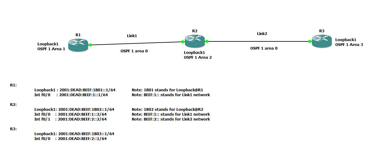
Setup OSPF Routing Protocol for IPv6 network


GNS3 has been used for this tutorial.
Assumption: You have basic knowledge of  CISCO and OSPF

  • IPv6 is 128 bits. Make life simple. Break it into two 64 bits. First 64 bits for network and second 64 bits for interface.You can break first 64 network bits into Global Unicast Prefix(48 bits) and Subnet(64 minus 48 = 16 bits).
  • OSPF is a link state dynamic routing protocol and it maintains a topology of the configured area. Area 0 acts as backbone area. Area 0 maintains the topology for the entire network. All Areas must have single interface attached to Area 0.
  • It is best practice to create Loopback 0 with IPv4 address that will be used by OSPF as Router-ID. For example: We used 192.168.1.1 for Router#1 and OSPF picks this address as Router-ID
R1(config)#interface loopback 0
R1(config-if)#ip address 192.168.1.1 255.255.255.0
R1(config-if)#no shut

  • Enable IPv6 unicast-routing and create OSPF router process. For example @ Router1
R1(config)#ipv6 unicast-routing
R1(config)#ipv6 router ospf 1
R1(config-rtr)#exit

  • For this tutorial, create Loopback 1 with IPv6 address and assign it to OSPF Area N (1 if it is Router1, 2 if it Router2). For example @ Router1
R1(config)#interface loopback 1
R1(config-if)# ipv6 address 2001:DEAD:BEEF:1B01::1/64
R1(config-if)# ipv6 ospf network point-to-point
R1(config-if)# ipv6 ospf 1 area 1

  • Configure IPv6 addresses on the interfaces interconnecting routers and assign that interface to OSPF Area 0 (Area 0 is the backbone area). For example @ Router1
R1(config)#interface f0/0
R1(config-if)#ipv6 address 2001:DEAD:BEEF:1::1/64
R1(config-if)#ipv6 ospf 1 area 0

  • Finally, check the IPv6 OSPF routing table and perform ping tests.
R1#sh ipv6 ospf neighbor
Neighbor ID     Pri   State           Dead Time   Interface ID    Interface
192.168.2.1       1   FULL/DR         00:00:38    4               FastEthernet0/0

R1#sh ipv6 route ospf
IPv6 Routing Table - 9 entries
Codes: C - Connected, L - Local, S - Static, R - RIP, B - BGP
       U - Per-user Static route
       I1 - ISIS L1, I2 - ISIS L2, IA - ISIS interarea, IS - ISIS summary
       O - OSPF intra, OI - OSPF inter, OE1 - OSPF ext 1, OE2 - OSPF ext 2
       ON1 - OSPF NSSA ext 1, ON2 - OSPF NSSA ext 2
O   2001:DEAD:BEEF:2::/64 [110/2]
     via FE80::C601:23FF:FE9C:0, FastEthernet0/0
OI  2001:DEAD:BEEF:1B02::/64 [110/2]
     via FE80::C601:23FF:FE9C:0, FastEthernet0/0
OI  2001:DEAD:BEEF:1B03::/64 [110/2]
     via FE80::C601:23FF:FE9C:0, FastEthernet0/0


Router configurations:
Router1#
!

ipv6 unicast-routing
!

!
interface Loopback0
 ip address 192.168.1.1 255.255.255.0
!
interface Loopback1
 no ip address
 ipv6 address 2001:DEAD:BEEF:1B01::1/64
 ipv6 ospf network point-to-point
 ipv6 ospf 1 area 1
!
interface FastEthernet0/0
 no ip address
 duplex auto
 speed auto
 ipv6 address 2001:DEAD:BEEF:1::1/64
 ipv6 ospf 1 area 0
!

!
ipv6 router ospf 1
 log-adjacency-changes
!

Router2#
!
ipv6 unicast-routing

!
interface Loopback0
 ip address 192.168.2.1 255.255.255.0
!
interface Loopback1
 no ip address
 ipv6 address 2001:DEAD:BEEF:1B02::1/64
 ipv6 ospf network point-to-point
 ipv6 ospf 1 area 2
!
interface FastEthernet0/0
 no ip address
 duplex auto
 speed auto
 ipv6 address 2001:DEAD:BEEF:1::2/64
 ipv6 ospf 1 area 0
!
interface FastEthernet0/1
 no ip address
 duplex auto
 speed auto
 ipv6 address 2001:DEAD:BEEF:2::2/64
 ipv6 ospf 1 area 0
!

!
ipv6 router ospf 1
 log-adjacency-changes
!
!


Router3#
!
ipv6 unicast-routing
!

!
interface Loopback0
 ip address 192.168.3.1 255.255.255.0
!
interface Loopback1
 no ip address
 ipv6 address 2001:DEAD:BEEF:1B03::1/64
 ipv6 ospf 1 area 3
!
interface FastEthernet0/0
 no ip address
 duplex auto
 speed auto
 ipv6 address 2001:DEAD:BEEF:2::1/64
 ipv6 ospf 1 area 0
!
!
ipv6 router ospf 1
 log-adjacency-changes
!
!


CISCO Bonus tips: 
How to setup SSH login in my Cisco router?
Ans: Following set of commands will create user 'admin' with password 'cisco'. RSA keys will be generated for encryption and authentication. Telnet will be disabled (Telnet is bad as there is no encryption involved) and SSH will be enabled.


conf t
 username admin privilege 15 secret cisco
 crypto key generate rsa general-keys label myrouterkey modulus 2048 

 ip ssh rsa keypair-name myrouterkey

 line vty 0 4
 login local
 transport input ssh


Wednesday, April 3, 2013

Setup secure firewall in Linux : iptables and netfilter

In Linux, components of netfilter and iptables are responsible for the filtering and manipulation of network packets.
The filtering criteria and actions are stored in chains, which must be matched one after another for each  network packets. The chains to match are stored in tables. The iptables command allows to alter these tables and rule sets. 
Check out the switches of iptables command 
#iptables -h 

Most frequently used switches are -t , -j, -A, -F, -p, -s, -d, -i and -o
-t table        table to manipulate (default: `filter')
-j target       target for rule (may load target extension)
-A chain            Append to chain
-F [chain]          Delete all rules in  chain or all chains
-p proto        protocol: by number or name, eg. `tcp'
-i  in-interface 
-o  out-interface

There are three different tables for Linux based firewall, each for a particular function:
  1. FILTER (Packet filtering; This table holds the filter rules that determine whether to ACCEPT or DROP packet)
  2. NAT (Masquerading; This table defines any changes to the source and target address of packets)
  3. MANGLE (The rules in this table allows IP header manipulation)
These tables contain several predefined chains to match packets:
  1. PREROUTING
  2. INPUT
  3. FORWARD
  4. OUTPUT
  5. POSTROUTING
Fig. iptables : Possible paths for a packet (Src: SLES Security book)


Let's start with some examples. Warning!!! Be very careful while executing iptables rules as you may lock yourself out of the server or disrupt network based services running on the server.

Basic Iptables operations: 
Note: Please follow the instructions step-by-step. Skipping steps is not advised.
  • Allow all kind of traffic(tcp/udp) from 192.168.1.0/24 subnet
  • Drop everything else
Rule1# iptables -A INPUT -s 192.168.1.0/255.255.255.0 -i eth0 -p all -j ACCEPT
(We are appending a rule to INPUT chain of FILTER table(default table). This rule checks if source address of the packet is in 192.168.1.0/24 subnet. If so, it will allow the traffic. Else, it will pass on to the next rule)

Rule2# iptables -A INPUT -s 0/0 -j DROP
(We are appending a rule to INPUT chain of FILTER table(default table). This rule drops everything else. Note: 0/0 means ANY )

Check the rules
         # iptables -vL --line-numbers
  • Now we want to INSERT a new rule after Rule#1. We want to allow UDP traffic from 10.0.0.0/8 subnet
NewRule# iptables -I INPUT 2 -s 10.0.0.0/255.0.0.0 -i  eth0 -p udp -j ACCEPT
(We are inserting a new rule as rule#2. This rules allows UDP traffic from 10.0.0.0/8 subnet)

Check the rules
         # iptables -vL --line-numbers

  • Now we want to REPLACE a new rule we just added earlier. We want to allow UDP traffic only from 10.11.0.0/16 subnet but not 10.0.0.0/8 subnet
ReplaceRule# iptables -R INPUT 2 -s 10.11.0.0/255.255.0.0 -i  eth0 -p udp -j ACCEPT
(We are replacing rule#2 with above rule. This rule allows UDP traffic from 10.11.0.0/16 subnet)

Check the rules
         # iptables -vL --line-numbers

  • Now we want to place this set of rules at system startup.
Let's say you validated all the rules and your system is working as desired. Now, you want to place this set of rules at system startup so that you don't have to type above commands manually again. 

#iptables-save > /etc/iptables.up.rules


#cd /etc/sysconfig/network/if-pre-up.d/
#vi iptables-load
#!/bin/sh
iptables-restore < /etc/iptables.up.rules
exit 0

#cd /etc/sysconfig/network/if-post-down.d/
#vi iptables-unload
#!/bin/sh
iptables-save -c > /etc/iptables.up.rules
if [ -f /etc/iptables.down.rules ]; then
   iptables-restore < /etc/iptables.down.rules
fi
exit 0
    #chmod +x iptables-load
    #chmod +x iptables-unload

Restart your server and check if rules are still there and your system is working as desired. 


Application1: Linux as NAT Router

Step1: Enable packet forwarding for IPv4
$ sudo vi /etc/sysctl.conf
# Uncomment the next line to enable packet forwarding for IPv4
net.ipv4.ip_forward=1


$ sudo sysctl -p /etc/sysctl.conf

Step2: MASQUERADE all the traffic leaving external interface (in our case eth1). MASQUERADE operation mask the private IP address of PC1 or PC2 with an external IP address of the Linux Router.
$ sudo /sbin/iptables -t nat -A POSTROUTING -o eth1 -j MASQUERADE

Step3: Forward all packets incoming from an internal interface (eth0) to external interface (eth1)
$ sudo /sbin/iptables -A FORWARD -i eth0 -o eth1 -j ACCEPT

Step4: Forward only RELATED and ESTABLISHED packets incoming from an external interface (eth1) to internal interface (eth0)
$ sudo  /sbin/iptables -A FORWARD -i eth1 -o eth0 -m state --state RELATED,ESTABLISHED -j ACCEPT

Step5: Check iptables
$ iptables -vL
OR
$ iptables -t filter -vL

To check NAT table
$ iptables -t nat -vL

[Note: if you don't specify table name using -t flag, default table 'filter' will be used ]

Step6: Try to get out to internet from PC1 or PC2. Say, browse www.google.com.

Bonus information:  Let's say you want to SSH  to PC2 (192.168.1.3 port 22) from an external network, you have to setup DNAT
Here, I am mapping port 11015 on an external IP address(Public Routable Address) of Linux Router to port 22 on PC2 which is in our internal network.


$   sudo iptables -t nat -A PREROUTING -p tcp --dport 11015 -j DNAT --to-destination 192.168.1.3:22
$  sudo iptables -A FORWARD -p tcp --dport 22 -d 192.168.1.3 -j ACCEPT
$  sudo iptables -t nat -A POSTROUTING -d 192.168.1.3 -p tcp --dport 22 -j MASQUERADE

Now, ssh  external_IP_address_of_LinuxRouter:11015 from an external network , you should get to 192.168.1.3:22.


Application2: Advanced Scenario (Firewall rules to mitigate an impact of DoS attack on Asterisk- VoIP Servers)

  • We want to delete all rules defined earlier and start fresh. We will be using 'hashlimit' match.
#iptables -F
  • Now, we want to define some advanced rules. We want to:
    • allow all packets from 192.168.1.0/24 subnet
    • limit the rate of SIP Invite from a host to mitigate DoS attack impact
    • limit the rate of SIP Registration from a host to mitigate DoS attack impact
    • allow all RTP(udp) traffic incoming from 10.0.0.0/8 subnet to ports 5000:31000(default RTP ports for asterisk)
    • drop any other packets
#iptables -A INPUT -s 192.168.1.0/255.255.255.0 -i eth0 -p all -j ACCEPT

#iptables -A INPUT -p udp -m udp --dport 5060 -m string --string "INVITE sip:" --algo bm -m hashlimit --hashlimit-upto 10/sec --hashlimit-burst 10 --hashlimit-mode srcip --hashlimit-name sip_i_limit -j ACCEPT

Look for the string "INVITE sip:" inside the UDP payload 
--hashlimit-upto   10/sec will allow upto 10 connection per second
--hashlimit-burst 10  will allow additional 10 packets before hit the limit (or how many fast connections you can have)
--hashlimit-htable-expire 10000   will expires hash entries in 10000 miliseconds

#iptables -A INPUT -p udp -m udp --dport 5060 -m string --string "REGISTER sip:" --algo bm -m hashlimit --hashlimit-upto 1/sec --hashlimit-burst 10 --hashlimit-mode srcip --hashlimit-name sip_r_limit -j ACCEPT

#iptables -A INPUT -s 10.0.0.0/8 -i eth2 -p udp -m udp --dport 5000:31000 -j ACCEPT
#iptables -A INPUT -s 0/0 -j DROP


  • We want to delete all rules defined earlier and start fresh. We will be using 'recent' match instead of 'hashlimit' match and achieve similar goal mentioned earlier to mitigate an impact of DoS attack.
#iptables -F

#iptables -A INPUT -s 192.168.1.0/255.255.255.0 -i eth0 -p all -j ACCEPT

#iptables -A INPUT 1 -i eth0 -p udp -m udp --dport 5060 -m string --string "REGISTER sip:" --algo bm --to 65535 -m recent --set --name VOIP --rsource

#iptables -A INPUT 1 -i eth0 -p udp -m udp --dport 5060 -m string --string "REGISTER sip:" --algo bm --to 65535 -m recent --update --seconds 60 --hitcount 12 --rttl --name VOIP --rsource -j DROP
Note: The maximum value for the hitcount parameter is given by the "ip_pkt_list_tot" parameter of the xt_recent kernel module. Exceeding this value on the command line will cause the rule to be rejected.

#iptables -A INPUT 1 -i eth0 -p udp -m udp --dport 5060 -m string --string "INVITE sip:" --algo bm --to 65535 -m recent --set --name VOIPINV --rsource

#iptables -A INPUT 1 -i eth0 -p udp -m udp --dport 5060 -m string --string "INVITE sip:" --algo bm --to 65535 -m recent --update --seconds 60 --hitcount 12 --rttl --name VOIPINV --rsource -j DROP

#iptables -A INPUT 1 -s 10.0.0.0/8 -i eth0 -p udp -m udp --dport 5000:31000 -j ACCEPT

#iptables -A INPUT -s 0/0 -j DROP

Go to iptables manual ( #man iptables ) to understand about hashlimit and recent match in detail.

Tuesday, March 26, 2013

Telnet Automation using Python: Copy CISCO configs to TFTP server


Scenario:
Enterprise is using TELNET for CISCO management. It wants to design an automated script that will copy config (either startup-config or running-config) of the CISCO routers and switches to the TFTP server. TFTP server has separate folder for each routers.
There are the times when a network engineer forgets to copy router config to the TFTP server after he/she makes changes to CISCO config. This little python script can be scheduled to copy configs periodically saving network engineers from possible unforeseen havoc because they don't have backup copy of the router config and router has crashed.

Note: This Python script is based on  Python version 3.3. You can execute this script on both windows and linux/unix environment. You can download python from http://www.python.org/getit/. When you install python make sure that python is added to your system environment variables.


#File name: telnetautomation.py
#!/usr/bin/python
#Script starts here
import getpass
import sys
import telnetlib
import time

pwd1 = "user_exec_mode_password"
pwd2 = "privilege_exec_mode_password"
config = "startup-config"

#Create a list of router IP address, folder location and router hostname  

hostlist= [ ("router1_ip_address","plano","planoRouter1"),
            ("router2_ip_address","dallas","dallasRouter1"),
        ]

#Use for loop to telnet into each routers and execute commands
for host in hostlist:
    
    cmd1 = "en"
    cmd2 = "copy "+config+" tftp://tftp_server/cisco/"+host[1]+"/"+host[2]+".txt"
#copy startup-config  tftp://tftp_server/plano/planoRouter1.txt

    tn = telnetlib.Telnet(host[0])
    tn.set_debuglevel(5)

    time.sleep(2)
    tn.write(pwd1.encode('ascii') + b"\n")
    time.sleep(2)
    tn.write(cmd1.encode('ascii') + b"\n")
    time.sleep(2)
    tn.write(pwd2.encode('ascii') + b"\n")
    time.sleep(2)
    tn.write(cmd2.encode('ascii') + b"\n")
    time.sleep(2)
    tn.write(b"\n")
    time.sleep(2)
    tn.write(b"\n")
    time.sleep(2)
    tn.close()

sys.exit("operation completed")

#script ends here

[Note: TELNET is not my favorite protocol as it is very insecure. Communication is done in plain text. However, there are many enterprises still running this insecure protocol in their environment. Upgrade to SSH and disable TELNET in your environment if possible.]

Friday, February 1, 2013

How to host multiple SSL enabled sites on a single IP address using Apache?

In the past, only one SSL enabled website could be hosted on a single IP address and default port 443 due to the limitation of TLS negotiation. With an addition of SNI(Server Name Identification) extension to TLS, server can now host multiple SSL enables sites using VirtualHost directive.

Apache ( 2.2.12 or later ) using OpenSSL(0.9.8 or later)  incorporates SNI. Today many browsers with the latest updates support SNI too. However, there could be many users still using older version of browsers that don't support SNI. Thus,  you may run into an issue where those customers may only be able to access your default website not the others.

Apache Configuration :

    Listen 443
    NameVirtualHost *:443
    SSLStrictSNIVHostCheck off

<VirtualHost *:443>
        ServerName  website1.yourdomain.com
        DocumentRoot /usr/local/your-website1/
----
----
</VirutalHost>

<VirtualHost *:443>
        ServerName  website2.yourdomain.com
        DocumentRoot /usr/local/your-website2/
----
----
</VirutalHost>


  • NameVirtualHost  apache directive is required if you want to configure name-based virtual hosts.
  • If SSLStrictSNIVHostCheck is off, then the request will be handled as if the server did not have SNI support.


Note: In Ubuntu, make changes appropriately to ports.conf and sites-enabled/your-ssl-websites  configuration files. In SLES, make changes appropriately  to listen.conf and vhosts.d/your-ssl-websites configuration files.


Additional Info:
Q: How to create SSL self signed certificate?
Ans: You can follow 4 basic steps:
    Step1: Generate no pass-phrase server private key; Note you can use any name for the key and certs. I prefer to use website URL as it is easier to track.
            #openssl genrsa -out website1.yourdomain.com.key 2048
    Step2: Generate CSR(Certificate Signing Request) using server private key
           #openssl req -new -key website1.yourdomain.com.key -out website1.yourdomain.com.csr
   Step3: Generate certificate using CSR and server private key.
           #openssl x509 -req -days 730 -in website1.yourdomain.com.csr  
-signkey website1.yourdomain.com.key -out website1.yourdomain.com.crt
   Step4: Copy certs and keys to appropriate location. In Linux, you can copy private keys to /etc/ssl/private and certificates to /etc/ssl/certs/

Q: How can I view the details of a certificate?
Ans: You can use the following command 
 #openssl x509 -in website1.yourdomain.com.crt -text

You can see that Certificate contains the reference to the issuer, the public key of the owner of this certificate, the dates of validity of this certificate and the signature of the certificate to ensure this certificate hasn't been tampered with. The certificate does not contain the private key as it should never be transmitted in any form whatsoever. This certificate has all the elements to send an encrypted message to the owner (using the public key) or to verify a message signed by the author of this certificate.

Q: How can I deploy SSL key and certificate in Apache?
Ans: You can follow 2 basic steps:
  Step1: Update VirtualHost configuration with the information of  SSL key and certificate you created.

    <VirtualHost *:443>
        ServerName  website1.yourdomain.com
        DocumentRoot /usr/local/your-website1/   
        SSLCertificateFile    /etc/ssl/certs/website1.yourdomain.com.crt
        SSLCertificateKeyFile /etc/ssl/private/website1.yourdomain.com.key
   </VirutalHost>


  Step2: Reload apache
         #service apache2 reload

Q: How SSL works?
Ans
Read notes from Symantec.com , tldp.org and luxsci.com

Basic steps (reference: tldp.org):
  1. A browser requests a secure page (usually https://).
  2. The web server sends its public key with its certificate. Note: Usually Certificate is signed with a private key of trusted Certificate Authority (e.g Verisign, Thwate, GoDaddy,etc). You can self sign a cert as demonstrated above if you don't want to pay for CSR. 
  3. All the browser comes installed with public key of all trusted Certificate Authority. The browser uses the public key to verify that the certificate was issued by a trusted root CA and certificate is still valid and that the certificate is related to the site contacted. If certificate is not signed by trusted CA, browser will complain that "Site's certificate is not trusted!".
  4. The browser then uses web server's public key to encrypt a random symmetric encryption key and sends it to the server with the encrypted URL required as well as other encrypted http data.
  5. The web server decrypts the symmetric encryption key using its private key and uses the symmetric key to decrypt the URL and http data.
  6. The web server sends back the requested html document and http data encrypted with the symmetric key.
  7. The browser decrypts the http data and html document using the symmetric key and displays the information.


Reference:

Wednesday, January 30, 2013

SNMP ObjectID Hierarchy


SNMP MIB Object tree/name space is hierarchical in structure rooted at root(.). This structure allows each manageable object to have its own globally unique name. This structure made SNMP modular. Each name space can be expanded without interfering/consulting with other name space or internet authority.
For example: name space assigned to CISCO is .1.3.6.1.4.1.9 [ root.iso.org.dod.internet.private. enterprises.cisco ] which is defined in CISCO-SMI MIB file and CISCO has the authority to assign names to objects anywhere below that name space. Object Identifier(OID) is written as a sequence of sub-identifiers separated with a period, starting at the root and ending at the object.

For in-depth explanation, refer to RFCs for SMI(Structure of Management Information):  RFC1155 (SNMP-SMI) and RFC2578 (SNMPv2-SMI)

Use CISCO OID Translator and Object Tree browser for more insights.

You can also look into MIB files to understand each network/device management objects.
In Linux, you should be able to locate MIB files under /usr/local/share/snmp/mibs
In Windows, you should be able to locate MIB files under %systemroot%\system32

Click here for basic tutorial on SNMP.
Install net-snmp if your system doesn't have snmp commands like snmpwalk, snmpget, snmpbulkget, etc.

snmpwalk is the easiest command to start with.
#snmpwalk -v <version>  -c  <Community_String>  -m ALL  <IP_ADDRESS_or_Domain_Name>   <Object_Name_or_Object_ID>

OPTIONS:
  -v 1|2c|3             specifies SNMP version to use
  -c COMMUNITY          set the community string
  -m MIB[:...]          load given list of MIBs (ALL loads everything)

Example1: To retrieve all SNMP objects under ISO for a network device(myserver.com):
#snmpwalk -v 2c  -c public  -m ALL  myserver.com   .1
or
#snmpwalk -v 2c -c public -m ALL myserver.com  iso

Example2: To retrieve all CISCO specific SNMP objects of a network device(myciscorouter.com) [ Note: For human readable objects, download CISCO specific MIB files and copy those files to /usr/local/share/snmp/mibs ]
#snmpwalk -v 2c  -c public  -m ALL  myciscorouter.com  .1.3.6.1.4.1.9
or
#snmpwalk -v 2c  -c public  -m ALL  myciscorouter.com   cisco

Wednesday, November 21, 2012

How big is IPv6?

IPv6 uses 128-bit addressing allowing 2128 addresses.

Analogy 1: Size based analogy

Say 1 IP address is equivalent to 1 picometer ( 10-12 meter = 0.000000000001 meter )
IPv4 is the size of an ant:  232 picometer = 4.29mm  
IPv6 is ridiculously large: (2128) picometers = 35 Billion light years
Note: 1 light year = 9.4605284 × 10¹² kilometers = 5.87849981 × 10¹² miles


Analogy 2: Weight based analogy
Say 1 speck of dust weighs 1 microgram
Mass of the Earth = 5.98 x 1027 grams = 5.98 x 1033 microgram
(Ref: http://en.wikipedia.org/wiki/Earth_mass)

Say Earth is made up of the dust particles


Total amount of the dust particles in Earth = 5.98 x 1033 which is equivalent to 2112


Total number of IPv6 Addresses: 2128

IPv6 address space is good enough to assign an IP address to each dust particles in  2(128-112)=216= 65536 planets the size of the earth.


Conclusion:
IPv6 address space allocation looks wasteful but it is so beautiful that you don't have to worry about conserving IP addresses any more as you can get ridiculously huge amount of address space. Now you can focus more on managing network rather than managing network address space itself. With that being said, proper IPv6 address planning is crucial otherwise it can get ugly and become a nightmare.

Wise principle to follow while doing IPv6 Address planning: Forget about IPv4 thinking, like address conservation, subnets, legacy class concepts, subnet masks (simply remember how to use CIDR style notation), etc. 


IPv6 is 128 bits. Make life simple. Break it into two 64 bits. First 64 bits for network and second 64 bits for interface.You can break first 64 network bits into Global Unicast Prefix(48 bits) and Subnet(64 minus 48 = 16 bits).


More yet to come... 

Thursday, March 8, 2012

Shared Line Appearance/Bridged Line Appearance in Asterisk

1.    Design Overview:

When someone calls Boss’ line, it will ring Boss’ as well as Assistants’ phone (Asterisk SLA/conference function and Line Trunking allows this feature).
Assistants can see the presence of their Boss’ line (Presence feature on Polycom phone and Asterisk HINT allows this).  Assistants can pick up the call by pressing the line button. Boss can join the conversation by pressing the line button as well (Barge In function, Asterisk Conference and Line Trunking allows us to do this)
You can simply put a call on hold from one phone and pick it up from another. Also, if multiple phones press the key for the shared extension, they will all be bridged into the same call(Asterisk SLA/conference function allows this feature).

2.    Terminologies:
  • Asterisk Technologies/Channels/Devices: There are various technologies/channels/devices available in Asterisk.
                Local
                SIP
                Agent
                & more ….

           Examples:
                 device=Local/disa@SLA_Outbound
           Defined  Local channel that lands the call in ‘disa’ extension of context [SLA_Outbound] in extensions.conf
  • DISA:  DISA (Direct Inward System Access) allows someone calling in from outside the telephone switch(PBX) to obtain an “internal” system dialtone and dial calls as if from one of the extensions attached to the telephone switch.  Check more @ http://www.voip-info.org/wiki/view/Asterisk+cmd+DISA
  • SLA: Shared Line Appearance
  • BLA: Bridged Line Appearance
  • Station: It is any SIP phone that will be using SLA
  • Trunk:  It is a literal trunk or shared extension that will be appearing on two or more stations
  • SLAStation() : Shared Line Appearance Station application. It should be executed by an SLA station. The argument to this application depends on how the call was initiated. If the phone was just taken off hook, then the argument ‘station’ should be just the station name. If the call was initiated by pressing a line key, then the station name should be preceded by an underscore and the trunk name associated with that line button.
      exten =>20000, n,SLAStation(20000)
      exten => 20000_line1,1,SLAStation(20000_line1)
  •  SLATrunk(): Shared Line Appearance Trunk application. This application takes care of ringing of all the appropriate stations.   

exten => 20000,1,Verbose(1,### Dialing trunk line1)
        same => n,Goto(sla,1)

exten => sla,1,SLATrunk(line1)


3.    Implementation:
  • Check if all the required Asterisk applications are installed properly
SLA application uses two key technologies: Device State Processing and Conferencing. Conferencing uses MeetMe() application. MeetMe() application is offered by app_meetme module. App_meetme module requires DAHDI to be installed (even if you don’t use PRIs).
Warning!!!
You have to load dahdi and dahdi_dummy before you start asterisk. You can check if those are loaded or not.
# lsmod|grep dahdi
dahdi                 210879  0
crc_ccitt               1651  1 dahdi


If you don’t get output like above, you might want to load it manually
#modprobe dahdi
#modprobe dahdi_dummy

Now check if app_meetme module is loaded or not.
*CLI> module show like app_meetme.so
Module                         Description                              Use Count
app_meetme.so                  MeetMe conference bridge                 0
1 modules loaded


[If it says 0 modules loaded, double check if dahdi and dahdi_dummy are loaded successfully or not. You might also get “WARNING[15929]: app_meetme.c:1228 build_conf: Unable to open DAHDI pseudo device” for not having dahdi_dummy]
Check if SLAStation() and SLATrunk() applications are available
*CLI> core show applications like SLA
    -= Matching Asterisk Applications =-
            SLAStation:
              SLATrunk:
    -= 2 Applications Matching =-


  • Asterisk Configuration
You have to understand and edit sla.conf, extensions.conf and sip.conf.

Trunks and Stations are defined in sla.conf. Mapping of devices to trunks and stations are also done here.
Station: It is any SIP phone that will be using SLA
Trunk:  It is a literal trunk or shared extension that will be appearing on two or more stations

#sla.conf
[general]
attemptcallerid=yes

[line1]
type=trunk
device=Local/disa@SLA_Outbound

[line2]
type=trunk
device=Local/disa@SLA_Outbound

[station](!)  ;Template for stations 
type=station
trunk=line1
;trunk=line2

[20000](station)   ;Note:section name do not need to match SIP device name
device=SIP/20000

[20001](station)
device=SIP/20001


Warning!!!
Trunk must be tied up with a device. Otherwise it will crash asterisk.

Here, we defined
•    two trunks [line1] and [line2]
•    two stations [20000] and [20001]   

If you watch very closely on above configuration, you will see that
•    trunk [line1] is tied up with device=Local/disa@SLA_Outbound
•    stations [20000] and [20001] are tied up with  device=SIP/20000
and device=SIP/20001 and will use trunk [line1] as defined in [station](!)  template

In our current scenario, we will not be using trunk [line2] to simplify the demonstration.

You can verify those by executing ‘sla’ commands in asterisk
*CLI> sla show trunks

=============================================================
=== Configured SLA Trunks ===================================
=============================================================
===
=== ---------------------------------------------------------
=== Trunk Name:       line1
=== ==> Device:       Local/disa@SLA_Outbound
=== ==> AutoContext:  (none)
=== ==> RingTimeout:  (none)
=== ==> BargeAllowed: Yes
=== ==> HoldAccess:   Open
=== ==> Stations ...
===    ==> Station name: 20000
===    ==> Station name: 20001
===    ==> Station name: 20002
=== ---------------------------------------------------------
===
=== ---------------------------------------------------------
=== Trunk Name:       line2
=== ==> Device:       Local/disa@SLA_Outbound
=== ==> AutoContext:  (none)
=== ==> RingTimeout:  (none)
=== ==> BargeAllowed: Yes
=== ==> HoldAccess:   Open
=== ==> Stations ...
=== ---------------------------------------------------------
===
=============================================================


*CLI> sla show stations

=============================================================
=== Configured SLA Stations =================================
=============================================================
===
=== ---------------------------------------------------------
=== Station Name:    20000
=== ==> Device:      SIP/20000
=== ==> AutoContext: (none)
=== ==> RingTimeout: (none)
=== ==> RingDelay:   (none)
=== ==> HoldAccess:  Open
=== ==> Trunks ...
===    ==> Trunk Name: line1
===       ==> State:       SLA_TRUNK_STATE_IDLE
===       ==> RingTimeout: (none)
===       ==> RingDelay:   (none)
=== ---------------------------------------------------------
===
=== ---------------------------------------------------------
=== Station Name:    20001
=== ==> Device:      SIP/20001
=== ==> AutoContext: (none)
=== ==> RingTimeout: (none)
=== ==> RingDelay:   (none)
=== ==> HoldAccess:  Open
=== ==> Trunks ...
===    ==> Trunk Name: line1
===       ==> State:       SLA_TRUNK_STATE_IDLE
===       ==> RingTimeout: (none)
===       ==> RingDelay:   (none)
=== ---------------------------------------------------------
===

Asterisk dialplan (extensions.conf) allows to setup extension state hints and extensions that define how calls get into and out of an SLA setup.
#extensions.conf

[SLA_Stations]
exten => 20000,1,Verbose(1,### Incoming Call to extension${EXTEN})
        same => n, Dial(SIP/${EXTEN})

exten => 20000_line1,hint,SLA:20000_line1

exten => 20000_line1,1,SLAStation(20000_line1)) ;This puts the call thru' disa@SLA_Outbound as it forces the call thru' the trunk
    
exten => 20001,1,Verbose(1,### Incoming Call to SLAStation)
        same => n, Dial(SIP/${EXTEN})

exten => _X.,1,Verbose(1,### Incoming Call from ${CALLERID(name)} : ${CALLERID(num)}) 


CUSTOMIZE YOUR DIALPLAN ACCORDING TO YOUR ENVIRONMENT


[SLA_Outbound]
exten => disa,1,DISA(no-password,SLA_Outbound)

exten => _X.,1,Verbose(1,### Incoming Call from ${CALLERID(name)} : ${CALLERID(num)})
CUSTOMIZE YOUR DIALPLAN ACCORDING TO YOUR ENVIRONMENT
[External]
exten => 20000,1,Verbose(1,### Dialing trunk line1)
        same => n, SLATrunk(line1)

exten => _X.,1,Verbose(1,### Incoming Call from ${CALLERID(name)} : ${CALLERID(num)}) 


CUSTOMIZE YOUR DIALPLAN ACCORDING TO YOUR ENVIRONMENT

SIP users are defined in sip.conf. SIP users for SLA stations are assigned [SLA_Stations] context.

#sip.conf
context=External

[SLA-sip-phone](!) ;Template
type=friend
host=dynamic
secret=mysecretpassword
context=SLA_Stations

[20000](SLA-sip-phone)
callerid= "Boss" <20000>
mailbox=20000

[20001](SLA-sip-phone)
callerid= "Secretary" <20001>
mailbox=20001

[sip-phone](!) ;Template
type=friend
host=dynamic
secret=mysecretpassword
context=External

[20002](sip-phone)
callerid= "John Doe" <20002>
mailbox=20002


Here 20000 and 20001 are using SLA-sip-phone template, thus they land in [SLA_Stations] of dialplan
And 20002 is using sip-phone template and it lands in [External] context

  • Polycom phone configuration
For phone with extension 20001
Make sure that directories, buddies and presence features are enabled.
Then define the directory for the phone.

#[MAC-ADDRESS]-directory.xml


         Boss Line1
         20000_line1@mysipserver.phones
         1
         1


Similar configuration for phone with extension 20000

You can now start testing. Please remember that you have to customize your dialplan according to your environment. Good Luck!