Showing posts with label Network. Show all posts

Monday, August 12, 2013

Routing Protocols Basics : Must know

I like to classify routing protocols as following:

Class Algorithm Examples
Distance Vector(DV) Bellman-Ford Algorithm RIP, BGP
Link State Protocol(LSP) Dijkstra's Algoirthm OSPF, IS-IS
Advanced DV Bellman Ford + DUAL(Diffusing Update Algorithm) EIGRP

You can use multiple routing protocols in the same environment. Administrative Distance value is used for a selection of the best route when multiple routing protocols are in place. The lowest Administrative Distance value wins. For example: Static Routing is more trust worthy than EIGRP. EIGRP is more trust worthy than OSPF.

Main goal of Routing Protocol is a calculation of the optimum path. Fundamentally there are two base algorithms for the shortest path calculation:
  • Distance Vector (Bellman-Ford Algorithm)
    • Router sends a copy of routing table to it's neighbors
    • Periodic update
    • Slow convergence
    • Counting to infinity problem
      • Solutions to prevents count to infinity problem:
        • Define MAX count limit (e.g max 16 hop count in RIP; 15 hop count is the maximum diameter of RIP; Disadvantage: convergence is very slow i.e 15*30=450 seconds before routers know that network is not reachable)
        • Split Horizon: Don't advertise the route to the router from where it learned the route
        • Route Poisoning and Poisoning Reverse: If neighbor router goes down, router advertise that route is unreachable
[DV Analogy: When you are driving down to some place (say from Houston to Dallas), you look at the miles. If miles keep on going down, you know that you are heading in the right direction. ]
  • Links State Protocol (Dijkstra's Algorithm)
    • Router shares neighbors info with all the routers
    • No periodic update
    • Convergence is very fast (nearly 6 seconds)
    • Three different tables:
      • Adjacency Table
      • Topology Table
      • Forwarding Table
    • CPU and Memory intensive as changes in the network requires all the routers to update link state database, run the SPF algorithm, build the SPF tree and then rebuild the routing table.

Understanding Bellman-Ford Algorithm:

Understanding Dijkstra's Algorithm:
Really nice YouTube video:
http://www.youtube.com/watch?v=8Ls1RqHCOPw

Important notes to keep in mind:
  • Routing takes place at Layer 3(Network Layer). Packet Forwarding takes place at Layer 2(Data Layer).
  • MPLS (Multiprotocol Label Switching) is a mechanism that allows packet forwarding using labels, hence making it an independent of Protocol Type. It offers L3 VPN solution. MPLS is connection-oriented and packets are forwarded across pre-configured LSPs(Label Switched Paths).
[MPLS Analogy: Postal Service network uses ZIP code/ Postal Code as a label to forward your mail (could be anything like documents, TV, gifts, etc) to the recipient. After the mail reaches to the destination ZIP code/Postal code area, then actual address of the mail recipient is used to forward the mail. This process makes mail delivery much easier and efficient. MPLS works the same way.]
  • IGPs(RIP/OSPF/EIGRP) are used for routing within AS while EGP(BGP) is used for routing between different ASs. IGP is used to route within your own network and BGP is used when you are connecting to a network you don't control. 
[BGP/IGP Analogy: Considering US Interstate System: Interstates are BGP backbone and Interstates Exits are handoffs to IGPs ]
  • BGP relies on IGP for the routing table. If route is not in the table, BGP won't advertise it.
  • BGP (Border Gateway Protocol) is used to make core routing decisions on the Internet and decisions are made based on Path and Network Policies. BGP allows multihoming (connect to multiple ISPs) for better redundancy.
  • With MPLS in place inside providers network, BGP only need to be setup on PE(Provider Edge) routers.
  • VRF (Virtual Routing and Fowarding) allows multiple instances of a routing table to exist in a router and work simultaneously. VRF allows network path segmentation, thus increases network security. Thus, VRF is also referred as VPN routing and forwarding.
[ VRF Analogy: Running multiple VRFs on a router is just like running multiple Virtual Machines on a single hypervisor. Virtual Machines run independent of each other, likewise Routing Table of each VRFs are independent of each other. ].


>>>>>>Time to get your hand  dirty>>>>>>>

BGP Lab:


Scenario:
Customer edge router is connected to two different ISPs for redundancy.
IP Address and ASN info is shown in above topology.
Customer uses EIGRP for routing within it's own network. 
Customer uses BGP to connect to two different ISPs.

Step1: Configure IP addresses on the routers as show above

CPE-RTR-CORE#
interface Serial1/0
 ip address 169.153.1.2 255.255.255.0
 clockrate 64000
 no shut

CPE-RTR-EDGE#
interface Serial1/0
 ip address 169.153.1.1 255.255.255.0
 clockrate 64000
 no shut
interface FastEthernet0/0
 ip address 172.20.1.1 255.255.255.0
 no shut
interface FastEthernet0/1
 ip address 172.20.2.1 255.255.255.0
 no shut

ISP-1#
interface Loopback0
 ip address 2.2.2.2 255.255.255.0
 no shut
interface FastEthernet0/0
 ip address 172.20.1.2 255.255.255.0
 no shut

ISP-2#
interface Loopback0
 ip address 3.3.3.3 255.255.255.0
 no shut
interface FastEthernet0/0
 ip address 172.20.2.2 255.255.255.0
 no shut

Step2: Configure BGP

ISP-1#
router bgp 200
 network 2.2.2.0 mask 255.255.255.0
 neighbor 172.20.1.1 remote-as 100

ISP-2#
router bgp 300
 network 3.3.3.0 mask 255.255.255.0
 neighbor 172.20.2.1 remote-as 100

CPE-RTR-EDGE#
ip as-path access-list 10 permit ^$    
[Note: This allow only local routes being advertised to ISP. In other words, this filters internet routes from one ISP to go back to another ISP.]  

route-map localonly permit 10
 match as-path 10

router bgp 100
 network 169.153.1.0 mask 255.255.255.0
 neighbor 172.20.1.2 remote-as 200
 neighbor 172.20.1.2 route-map localonly out
 neighbor 172.20.2.2 remote-as 300
 neighbor 172.20.2.2 route-map localonly out

Detailed explaination on access-list and regex

Step3: Configure EIGRP 

CPE-RTR-CORE#
router eigrp 100
 network 169.153.1.0 0.0.0.255
 network 0.0.0.0 255.255.255.255  [This advertises all the routes known to this router]

CPE-RTR-EDGE#
router eigrp 100
 network 169.153.1.0 0.0.0.255
 network 0.0.0.0 255.255.255.255 [This advertises all the routes known to this router]


Some useful commands for troubleshooting:
#sh ip bgp
#sh ip bgp 
#sh ip bgp regexp ^$   [Display only local routes]
#sh ip bgp regexp ^100$  [Display routes learned from ASN 100 ]
#sh ip bgp regexp ^100_  [ Display routes with ASN 100 at front ]
#sh ip route
#clear bgp *   [Clear all BGP peers]
#debug bgp updates in
#debug bgp updates out


VRF Lab:


Scenario:
Say an ISP has two customers: Plano ISD (PISD) and Dallas ISD (DISD)
PISD and DISD both uses same subnet for IP addressing (172.20.0.0/24 & 172.20.1.0/24) and they can't change their addressing scheme.
As an ISP, you want to do business with both the customers. Your goal to isolate PISD network and DISD network ensuring network security. VRF is your solution.


Step1: Configure IP addresses on the routers as shown above

PISD1#
interface Loopback0
 ip address 1.1.1.1 255.255.255.0
interface FastEthernet0/0
 ip address 172.20.0.1 255.255.255.0

PISD2#
interface Loopback0
 ip address 2.2.2.2 255.255.255.0
interface FastEthernet0/0
 ip address 172.20.1.1 255.255.255.0

DISD1#
interface Loopback0
 ip address 1.1.1.1 255.255.255.0
interface Serial1/0
 ip address 172.20.0.1 255.255.255.0
 clockrate 64000

DISD2#
interface Loopback0
 ip address 2.2.2.2 255.255.255.0
interface Serial1/0
 ip address 172.20.1.1 255.255.255.0
 clockrate 64000

Note: You can't configure IP address on ISP router as it will throw an error that you are trying to configure duplicate IP address. In out network topology ISP s1/0 and f0/0 ports are going to have same IP address (i.e 172.20.0.2/24). ISP s1/1 and f0/1 are going to have same IP address (i.e 172.20.1.2/24).

Step2: Create VRF on ISP router and add interfaces to desired VRF so that you can configure IP address on ISP router to connect to CPE routers.

ISP#
ip vrf PISD
 rd 1:1
ip vrf DISD
 rd 2:2

Step3: Configure IP addresses on ISP router
ISP#
interface FastEthernet0/0
 ip vrf forwarding PISD
 ip address 172.20.0.2 255.255.255.0


interface FastEthernet0/1
 ip vrf forwarding PISD
 ip address 172.20.1.2 255.255.255.0

interface Serial1/0
 ip vrf forwarding DISD
 ip address 172.20.0.2 255.255.255.0
 clockrate 64000

interface Serial1/1
 ip vrf forwarding DISD
 ip address 172.20.1.2 255.255.255.0
 clockrate 64000

Step4: Configure OSPF on all the routers

CPE-ROUTERS(PISD1, PISD2, DISD1, DISD2)#
router ospf  1
 network 0.0.0.0 255.255.255.255 area 0 [This advertises all the routes known to this router]

ISP#
router ospf  1 vrf  PISD
 network 0.0.0.0 255.255.255.255 area 0 [This advertises all the routes known to this router]

router ospf  2 vrf  DISD
 network 0.0.0.0 255.255.255.255 area 0  [This advertises all the routes known to this router]

Some useful commands for troubleshooting:
#sh ip route
#sh ip route vrf  PISD
#sh ip router vrf DISD


Monday, May 6, 2013

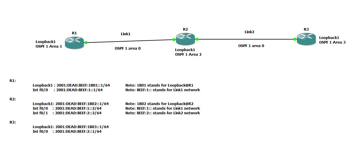
Setup OSPF Routing Protocol for IPv6 network


GNS3 has been used for this tutorial.
Assumption: You have basic knowledge of  CISCO and OSPF

  • IPv6 is 128 bits. Make life simple. Break it into two 64 bits. First 64 bits for network and second 64 bits for interface.You can break first 64 network bits into Global Unicast Prefix(48 bits) and Subnet(64 minus 48 = 16 bits).
  • OSPF is a link state dynamic routing protocol and it maintains a topology of the configured area. Area 0 acts as backbone area. Area 0 maintains the topology for the entire network. All Areas must have single interface attached to Area 0.
  • It is best practice to create Loopback 0 with IPv4 address that will be used by OSPF as Router-ID. For example: We used 192.168.1.1 for Router#1 and OSPF picks this address as Router-ID
R1(config)#interface loopback 0
R1(config-if)#ip address 192.168.1.1 255.255.255.0
R1(config-if)#no shut

  • Enable IPv6 unicast-routing and create OSPF router process. For example @ Router1
R1(config)#ipv6 unicast-routing
R1(config)#ipv6 router ospf 1
R1(config-rtr)#exit

  • For this tutorial, create Loopback 1 with IPv6 address and assign it to OSPF Area N (1 if it is Router1, 2 if it Router2). For example @ Router1
R1(config)#interface loopback 1
R1(config-if)# ipv6 address 2001:DEAD:BEEF:1B01::1/64
R1(config-if)# ipv6 ospf network point-to-point
R1(config-if)# ipv6 ospf 1 area 1

  • Configure IPv6 addresses on the interfaces interconnecting routers and assign that interface to OSPF Area 0 (Area 0 is the backbone area). For example @ Router1
R1(config)#interface f0/0
R1(config-if)#ipv6 address 2001:DEAD:BEEF:1::1/64
R1(config-if)#ipv6 ospf 1 area 0

  • Finally, check the IPv6 OSPF routing table and perform ping tests.
R1#sh ipv6 ospf neighbor
Neighbor ID     Pri   State           Dead Time   Interface ID    Interface
192.168.2.1       1   FULL/DR         00:00:38    4               FastEthernet0/0

R1#sh ipv6 route ospf
IPv6 Routing Table - 9 entries
Codes: C - Connected, L - Local, S - Static, R - RIP, B - BGP
       U - Per-user Static route
       I1 - ISIS L1, I2 - ISIS L2, IA - ISIS interarea, IS - ISIS summary
       O - OSPF intra, OI - OSPF inter, OE1 - OSPF ext 1, OE2 - OSPF ext 2
       ON1 - OSPF NSSA ext 1, ON2 - OSPF NSSA ext 2
O   2001:DEAD:BEEF:2::/64 [110/2]
     via FE80::C601:23FF:FE9C:0, FastEthernet0/0
OI  2001:DEAD:BEEF:1B02::/64 [110/2]
     via FE80::C601:23FF:FE9C:0, FastEthernet0/0
OI  2001:DEAD:BEEF:1B03::/64 [110/2]
     via FE80::C601:23FF:FE9C:0, FastEthernet0/0


Router configurations:
Router1#
!

ipv6 unicast-routing
!

!
interface Loopback0
 ip address 192.168.1.1 255.255.255.0
!
interface Loopback1
 no ip address
 ipv6 address 2001:DEAD:BEEF:1B01::1/64
 ipv6 ospf network point-to-point
 ipv6 ospf 1 area 1
!
interface FastEthernet0/0
 no ip address
 duplex auto
 speed auto
 ipv6 address 2001:DEAD:BEEF:1::1/64
 ipv6 ospf 1 area 0
!

!
ipv6 router ospf 1
 log-adjacency-changes
!

Router2#
!
ipv6 unicast-routing

!
interface Loopback0
 ip address 192.168.2.1 255.255.255.0
!
interface Loopback1
 no ip address
 ipv6 address 2001:DEAD:BEEF:1B02::1/64
 ipv6 ospf network point-to-point
 ipv6 ospf 1 area 2
!
interface FastEthernet0/0
 no ip address
 duplex auto
 speed auto
 ipv6 address 2001:DEAD:BEEF:1::2/64
 ipv6 ospf 1 area 0
!
interface FastEthernet0/1
 no ip address
 duplex auto
 speed auto
 ipv6 address 2001:DEAD:BEEF:2::2/64
 ipv6 ospf 1 area 0
!

!
ipv6 router ospf 1
 log-adjacency-changes
!
!


Router3#
!
ipv6 unicast-routing
!

!
interface Loopback0
 ip address 192.168.3.1 255.255.255.0
!
interface Loopback1
 no ip address
 ipv6 address 2001:DEAD:BEEF:1B03::1/64
 ipv6 ospf 1 area 3
!
interface FastEthernet0/0
 no ip address
 duplex auto
 speed auto
 ipv6 address 2001:DEAD:BEEF:2::1/64
 ipv6 ospf 1 area 0
!
!
ipv6 router ospf 1
 log-adjacency-changes
!
!


CISCO Bonus tips: 
How to setup SSH login in my Cisco router?
Ans: Following set of commands will create user 'admin' with password 'cisco'. RSA keys will be generated for encryption and authentication. Telnet will be disabled (Telnet is bad as there is no encryption involved) and SSH will be enabled.


conf t
 username admin privilege 15 secret cisco
 crypto key generate rsa general-keys label myrouterkey modulus 2048 

 ip ssh rsa keypair-name myrouterkey

 line vty 0 4
 login local
 transport input ssh


Wednesday, April 3, 2013

Setup secure firewall in Linux : iptables and netfilter

In Linux, components of netfilter and iptables are responsible for the filtering and manipulation of network packets.
The filtering criteria and actions are stored in chains, which must be matched one after another for each  network packets. The chains to match are stored in tables. The iptables command allows to alter these tables and rule sets. 
Check out the switches of iptables command 
#iptables -h 

Most frequently used switches are -t , -j, -A, -F, -p, -s, -d, -i and -o
-t table        table to manipulate (default: `filter')
-j target       target for rule (may load target extension)
-A chain            Append to chain
-F [chain]          Delete all rules in  chain or all chains
-p proto        protocol: by number or name, eg. `tcp'
-i  in-interface 
-o  out-interface

There are three different tables for Linux based firewall, each for a particular function:
  1. FILTER (Packet filtering; This table holds the filter rules that determine whether to ACCEPT or DROP packet)
  2. NAT (Masquerading; This table defines any changes to the source and target address of packets)
  3. MANGLE (The rules in this table allows IP header manipulation)
These tables contain several predefined chains to match packets:
  1. PREROUTING
  2. INPUT
  3. FORWARD
  4. OUTPUT
  5. POSTROUTING
Fig. iptables : Possible paths for a packet (Src: SLES Security book)


Let's start with some examples. Warning!!! Be very careful while executing iptables rules as you may lock yourself out of the server or disrupt network based services running on the server.

Basic Iptables operations: 
Note: Please follow the instructions step-by-step. Skipping steps is not advised.
  • Allow all kind of traffic(tcp/udp) from 192.168.1.0/24 subnet
  • Drop everything else
Rule1# iptables -A INPUT -s 192.168.1.0/255.255.255.0 -i eth0 -p all -j ACCEPT
(We are appending a rule to INPUT chain of FILTER table(default table). This rule checks if source address of the packet is in 192.168.1.0/24 subnet. If so, it will allow the traffic. Else, it will pass on to the next rule)

Rule2# iptables -A INPUT -s 0/0 -j DROP
(We are appending a rule to INPUT chain of FILTER table(default table). This rule drops everything else. Note: 0/0 means ANY )

Check the rules
         # iptables -vL --line-numbers
  • Now we want to INSERT a new rule after Rule#1. We want to allow UDP traffic from 10.0.0.0/8 subnet
NewRule# iptables -I INPUT 2 -s 10.0.0.0/255.0.0.0 -i  eth0 -p udp -j ACCEPT
(We are inserting a new rule as rule#2. This rules allows UDP traffic from 10.0.0.0/8 subnet)

Check the rules
         # iptables -vL --line-numbers

  • Now we want to REPLACE a new rule we just added earlier. We want to allow UDP traffic only from 10.11.0.0/16 subnet but not 10.0.0.0/8 subnet
ReplaceRule# iptables -R INPUT 2 -s 10.11.0.0/255.255.0.0 -i  eth0 -p udp -j ACCEPT
(We are replacing rule#2 with above rule. This rule allows UDP traffic from 10.11.0.0/16 subnet)

Check the rules
         # iptables -vL --line-numbers

  • Now we want to place this set of rules at system startup.
Let's say you validated all the rules and your system is working as desired. Now, you want to place this set of rules at system startup so that you don't have to type above commands manually again. 

#iptables-save > /etc/iptables.up.rules


#cd /etc/sysconfig/network/if-pre-up.d/
#vi iptables-load
#!/bin/sh
iptables-restore < /etc/iptables.up.rules
exit 0

#cd /etc/sysconfig/network/if-post-down.d/
#vi iptables-unload
#!/bin/sh
iptables-save -c > /etc/iptables.up.rules
if [ -f /etc/iptables.down.rules ]; then
   iptables-restore < /etc/iptables.down.rules
fi
exit 0
    #chmod +x iptables-load
    #chmod +x iptables-unload

Restart your server and check if rules are still there and your system is working as desired. 


Application1: Linux as NAT Router

Step1: Enable packet forwarding for IPv4
$ sudo vi /etc/sysctl.conf
# Uncomment the next line to enable packet forwarding for IPv4
net.ipv4.ip_forward=1


$ sudo sysctl -p /etc/sysctl.conf

Step2: MASQUERADE all the traffic leaving external interface (in our case eth1). MASQUERADE operation mask the private IP address of PC1 or PC2 with an external IP address of the Linux Router.
$ sudo /sbin/iptables -t nat -A POSTROUTING -o eth1 -j MASQUERADE

Step3: Forward all packets incoming from an internal interface (eth0) to external interface (eth1)
$ sudo /sbin/iptables -A FORWARD -i eth0 -o eth1 -j ACCEPT

Step4: Forward only RELATED and ESTABLISHED packets incoming from an external interface (eth1) to internal interface (eth0)
$ sudo  /sbin/iptables -A FORWARD -i eth1 -o eth0 -m state --state RELATED,ESTABLISHED -j ACCEPT

Step5: Check iptables
$ iptables -vL
OR
$ iptables -t filter -vL

To check NAT table
$ iptables -t nat -vL

[Note: if you don't specify table name using -t flag, default table 'filter' will be used ]

Step6: Try to get out to internet from PC1 or PC2. Say, browse www.google.com.

Bonus information:  Let's say you want to SSH  to PC2 (192.168.1.3 port 22) from an external network, you have to setup DNAT
Here, I am mapping port 11015 on an external IP address(Public Routable Address) of Linux Router to port 22 on PC2 which is in our internal network.


$   sudo iptables -t nat -A PREROUTING -p tcp --dport 11015 -j DNAT --to-destination 192.168.1.3:22
$  sudo iptables -A FORWARD -p tcp --dport 22 -d 192.168.1.3 -j ACCEPT
$  sudo iptables -t nat -A POSTROUTING -d 192.168.1.3 -p tcp --dport 22 -j MASQUERADE

Now, ssh  external_IP_address_of_LinuxRouter:11015 from an external network , you should get to 192.168.1.3:22.


Application2: Advanced Scenario (Firewall rules to mitigate an impact of DoS attack on Asterisk- VoIP Servers)

  • We want to delete all rules defined earlier and start fresh. We will be using 'hashlimit' match.
#iptables -F
  • Now, we want to define some advanced rules. We want to:
    • allow all packets from 192.168.1.0/24 subnet
    • limit the rate of SIP Invite from a host to mitigate DoS attack impact
    • limit the rate of SIP Registration from a host to mitigate DoS attack impact
    • allow all RTP(udp) traffic incoming from 10.0.0.0/8 subnet to ports 5000:31000(default RTP ports for asterisk)
    • drop any other packets
#iptables -A INPUT -s 192.168.1.0/255.255.255.0 -i eth0 -p all -j ACCEPT

#iptables -A INPUT -p udp -m udp --dport 5060 -m string --string "INVITE sip:" --algo bm -m hashlimit --hashlimit-upto 10/sec --hashlimit-burst 10 --hashlimit-mode srcip --hashlimit-name sip_i_limit -j ACCEPT

Look for the string "INVITE sip:" inside the UDP payload 
--hashlimit-upto   10/sec will allow upto 10 connection per second
--hashlimit-burst 10  will allow additional 10 packets before hit the limit (or how many fast connections you can have)
--hashlimit-htable-expire 10000   will expires hash entries in 10000 miliseconds

#iptables -A INPUT -p udp -m udp --dport 5060 -m string --string "REGISTER sip:" --algo bm -m hashlimit --hashlimit-upto 1/sec --hashlimit-burst 10 --hashlimit-mode srcip --hashlimit-name sip_r_limit -j ACCEPT

#iptables -A INPUT -s 10.0.0.0/8 -i eth2 -p udp -m udp --dport 5000:31000 -j ACCEPT
#iptables -A INPUT -s 0/0 -j DROP


  • We want to delete all rules defined earlier and start fresh. We will be using 'recent' match instead of 'hashlimit' match and achieve similar goal mentioned earlier to mitigate an impact of DoS attack.
#iptables -F

#iptables -A INPUT -s 192.168.1.0/255.255.255.0 -i eth0 -p all -j ACCEPT

#iptables -A INPUT 1 -i eth0 -p udp -m udp --dport 5060 -m string --string "REGISTER sip:" --algo bm --to 65535 -m recent --set --name VOIP --rsource

#iptables -A INPUT 1 -i eth0 -p udp -m udp --dport 5060 -m string --string "REGISTER sip:" --algo bm --to 65535 -m recent --update --seconds 60 --hitcount 12 --rttl --name VOIP --rsource -j DROP
Note: The maximum value for the hitcount parameter is given by the "ip_pkt_list_tot" parameter of the xt_recent kernel module. Exceeding this value on the command line will cause the rule to be rejected.

#iptables -A INPUT 1 -i eth0 -p udp -m udp --dport 5060 -m string --string "INVITE sip:" --algo bm --to 65535 -m recent --set --name VOIPINV --rsource

#iptables -A INPUT 1 -i eth0 -p udp -m udp --dport 5060 -m string --string "INVITE sip:" --algo bm --to 65535 -m recent --update --seconds 60 --hitcount 12 --rttl --name VOIPINV --rsource -j DROP

#iptables -A INPUT 1 -s 10.0.0.0/8 -i eth0 -p udp -m udp --dport 5000:31000 -j ACCEPT

#iptables -A INPUT -s 0/0 -j DROP

Go to iptables manual ( #man iptables ) to understand about hashlimit and recent match in detail.

Tuesday, March 26, 2013

Telnet Automation using Python: Copy CISCO configs to TFTP server


Scenario:
Enterprise is using TELNET for CISCO management. It wants to design an automated script that will copy config (either startup-config or running-config) of the CISCO routers and switches to the TFTP server. TFTP server has separate folder for each routers.
There are the times when a network engineer forgets to copy router config to the TFTP server after he/she makes changes to CISCO config. This little python script can be scheduled to copy configs periodically saving network engineers from possible unforeseen havoc because they don't have backup copy of the router config and router has crashed.

Note: This Python script is based on  Python version 3.3. You can execute this script on both windows and linux/unix environment. You can download python from http://www.python.org/getit/. When you install python make sure that python is added to your system environment variables.


#File name: telnetautomation.py
#!/usr/bin/python
#Script starts here
import getpass
import sys
import telnetlib
import time

pwd1 = "user_exec_mode_password"
pwd2 = "privilege_exec_mode_password"
config = "startup-config"

#Create a list of router IP address, folder location and router hostname  

hostlist= [ ("router1_ip_address","plano","planoRouter1"),
            ("router2_ip_address","dallas","dallasRouter1"),
        ]

#Use for loop to telnet into each routers and execute commands
for host in hostlist:
    
    cmd1 = "en"
    cmd2 = "copy "+config+" tftp://tftp_server/cisco/"+host[1]+"/"+host[2]+".txt"
#copy startup-config  tftp://tftp_server/plano/planoRouter1.txt

    tn = telnetlib.Telnet(host[0])
    tn.set_debuglevel(5)

    time.sleep(2)
    tn.write(pwd1.encode('ascii') + b"\n")
    time.sleep(2)
    tn.write(cmd1.encode('ascii') + b"\n")
    time.sleep(2)
    tn.write(pwd2.encode('ascii') + b"\n")
    time.sleep(2)
    tn.write(cmd2.encode('ascii') + b"\n")
    time.sleep(2)
    tn.write(b"\n")
    time.sleep(2)
    tn.write(b"\n")
    time.sleep(2)
    tn.close()

sys.exit("operation completed")

#script ends here

[Note: TELNET is not my favorite protocol as it is very insecure. Communication is done in plain text. However, there are many enterprises still running this insecure protocol in their environment. Upgrade to SSH and disable TELNET in your environment if possible.]

Monday, October 10, 2011

Configured server with multiple NICs on different subnet. Can't PING IP add on second NIC? Here's the solution

Let's say you have a network access problem as shown below (User can't access 10.1.1.10 from the workstation. User fails to ping 10.1.1.10 from workstation):


Note: In Linux, usually NIC1 is presented as eth0 and NIC2 is presented as eth1

How to fix the problem associated with accessing 10.1.1.10 from workstation?

You must configure multiple default routes in the server.
You can possibly achieve this in different ways, however I prefer the use of IP ROUTE and IP RULES. It's easy to implement and understand.

Step 1: Create a new policy routing table
# echo "1 TenNetwork" >> /etc/iproute2/rt_tables

Routing tables are declared in rt_tables. Here we declared TenNetwork table as we are going to write a set of rules associated with 10 network. You can give it any name you want.

Step2: Define routes in the table
#ip route add 10.1.0.0/16 dev eth1 src 10.1.1.10 table TenNetwork

#ip route add default via 10.1.1.1 dev eth1 table TenNetwork

Here we simply declared that NIC2(eth1) is associated with 10.1.0.0 subnet and it's IP address is 10.1.1.10. We also defined the default route via 10.1.1.1 on eth1 interface. (This is second default route. The first one is defined in 'main' routing table and the default route is via 192.168.2.1 on eth0 interface. OS automatically picks the first default route from eth0. You can check that by executing #ip rule show or #netstat -anr command)

#ip rule show

Since we haven't defined any rule associated with TenNetwork table yet, we can't see TenNetwork table in the rules.

Step3: Define the rules associated with TenNetwork table

#ip rule add from 10.1.1.10/32 table TenNetwork
#ip rule add to 10.1.1.10/32 table TenNetwork

Here we are defining a rule that says, if any packet is FROM/TO to 10.1.1.10, lookup the TenNetwork table.

#ip rule show
#netstat -anr

Now you can see the active routing rules associated with TenNetwork table as well.

You should be able to ping 10.1.1.10 from workstation now.

Run WireShark on the server before and after applying the rule. You can visualize the problem and see how the problem is resolved.


Warning!!!! :
1. Restarting the server will cause the configuration loss
2. Restarting the network will cause the configuration loss

Let's solve this configuration loss issue associated with restarting the server/network. We will write a startup script.

#vi /etc/init.d/TenNetwork
#!/bin/bash
#Copyright (c) 2011 DShah
# All rights reserved
#
#Author: DShah, 2011
# /etc/init.d/TenNetwork
#PLEASE READ /etc/init.d/skeleton to understand various parameters in startup scripts
#
### BEGIN INIT INFO
# Provides: TenNetwork
# Required-Start: $network
# Required-Stop:
# Default-Start: 3 5
# Default-Stop: 0 1 2 6
# Short-Description: Fixes 10 Network routing issue
### END INIT INFO

$logFile=/var/log/ten-network-log
ip route add 10.1.0.0/16 dev eth1 src 10.1.1.10 table TenNetwork
ip route add default via 10.1.1.1 dev eth1 table TenNetwork
ip route show 2>&1 >> $logFile
ip rule add from 10.1.1.10/32 table TenNetwork
ip rule add to 10.1.1.10/32 table TenNetwork
ip rule show 2>&1 >> $logFile
ip route show 2>&1 >> $logFile

Save and close the file

#chmod 700 /etc/init.d/TenNetwork

'insserv' command can be used to insert the script in desired runlevel as specified in script file
# insserv TenNetwork

You can go to /etc/init.d/rc3.d and /etc/init.d/rc5.d and look the startup order of TenNetwork.

Restart your server and see if it is working as you expected.


Updated info on 03/28/13 [Easy fix ]:

Multiple NICs routing issue can be resolved by making some modification in systctl.conf

/etc/sysctl.conf
# Disable response to broadcasts.
# You don't want yourself becoming a Smurf amplifier.
net.ipv4.icmp_echo_ignore_broadcasts = 1
# Disable route verification on all interfaces
net.ipv4.conf.all.rp_filter = 0
# enable ipV6 forwarding
#net.ipv6.conf.all.forwarding = 1
# increase the number of possible inotify(7) watches
fs.inotify.max_user_watches = 65536
# avoid deleting secondary IPs on deleting the primary IP
net.ipv4.conf.default.promote_secondaries = 1
net.ipv4.conf.all.promote_secondaries = 1


#sysctl -p   (to reload the changes done on the sysctl config)


Reference:
http://www.policyrouting.org/PolicyRoutingBook/ONLINE/TOC.html

Tuesday, March 8, 2011

VLAN : 5 mintue reading to get the core concept of VLAN implementation

VLAN (Virtual LAN) is the logical technique that enables hosts across various LANs to communicate with each other as if they are on same LAN/wire.

VLAN splits the broadcast domain as host on one VLAN can't talk with host on another VLAN without the help of Layer 3 device.

There are two types of the switch port operation mode:

Trunk Mode: Allows multiple VLAN ID to pass through; Usually FastEthernet 0/24 port or GigabitEthernet port for inter-switch link. Multiple switches are interconnected via link connected to the port in Trunk mode.

Access Mode: Allows only one VLAN ID; Hosts are connected to the ports defined as Access mode. By default all ports on the switch are in Access Mode.


Let's see how to define VLAN, add interface/switch ports to VLAN and define TRUNK port

[ In this example we have FinanceDept and HumanResourceDept and we want to separate them using VLAN]

>en
Switch#config term
Switch#hostname Switch1

Switch1-config# vlan 2
Switch1-config-vlan#name HumanResourceDept

Switch1-config-vlan#vlan 3
Switch1-config-vlan#name FinanceDept

Switch1-config-vlan#exit
Switch1-config#exit

Switch1#show vlan
(Find which ports are being used by HumanResourceDept hosts and FinanceDept hosts; say F0/1,F0/2 are being used by HumanResourceDept hosts and F0/3 and F0/4 are being used by FinanceDept hosts)

Switch1#config term
Switch1-config#int F0/1
Switch1-config-if#switchport access vlan 2
Switch1-config-if#int F0/2
Swtich1-config-if#switchport access vlan 2

Switch1-config#int F0/3
Switch1-config-if#switchport access vlan 3
Switch1-config-if#int F0/4
Swtich1-config-if#switchport access vlan 3

Switch1-config-if# [press Ctrl + z]
Switch1#

Now check, if F0/1 and F0/2 are assigned to VLAN 2 , similarly check if F0/3 and F0/4 are assigned to VLAN 3

Switch1#show vlan

Now, hosts belonging to HumanResourceDept connected to Port F0/1 and F0/2 should be able to talk to each other. Perfom ping test.
Similarly do the test with FinanceDept hosts

VERY VERY IMPORTANT CONCEPTS:
>> Hosts on same vlan *must* has same subnet number. For example HumanResourceDept hosts should be under same subnet e.g 192.168.1.0/24 like Host1 IP: 192.168.1.2/24 Host2 IP: 192.168.1.3/24

>> Layer 3 device is required to establish communication between different VLANs


Now, lets define Trunk port on Switch1 so that we can interconnect it to another switch Switch2.

Switch1#config term
Switch1-config#int F0/24
Switch1-config-if#switchport mode trunk

Switch1-config-if# [Press Ctrl + z]

Switch1#show interface trunk

[This will show that F0/24 passes all the VLAN from one switch to another switch. Thus TRUNK mode is only enabled on FastEthernet port and GigabitEthernet port as it requires high bandwidth to pass all VLAN]

Do the same on Switch2

Switch>en
Switch#hostname Switch2

Switch2#config term
Switch2-config#int F0/24
Switch2-config-if#switchport mode trunk

Switch2-config-if# [Press Ctrl + z]

Switch2#show interface trunk


Let's say there is one host of FinanceDept plugged in on port F0/10 of switch2. For the hosts of FinanceDept on switch1 to talk with host on switch2, you have to define VLAN on switch2 and add the desired access port (here in our example: it's port F0/10 on that vlan 3).

Switch2#config term
Switch2-config#int F0/10
Switch2-config-if#switchport access vlan 3

Now, perform ping test between hosts of FinanceDept plugged in to Switch1 and Switch2. [ Friendly reminder: Hosts on same vlan should have same subnet number.]

Monday, February 14, 2011

Console Port Connection in Cisco Routers

The router has an EIA/TIA-232 asynchronous serial console port (RJ-45). Depending on the cable and the adapter used, this port appears as a DTE or DCE device at the end of the cable.

For connection to a PC running terminal emulation software e.g HyperTerminal in Windows machine, router is provided with an RJ-45 to DB-9 adapter cable (blue cable).

The default parameters for the console port are 9600 baud, 8 data bits, 1 stop bit, and no parity. The console port does not support hardware flow control.

For general overview of Hardware installation and Software configuration, please go thru' following links:

Hardware Installation

Software Configuration with upgrade techniques